If you ever tried to create a counter in a logic simulator, chances are that you have created a state machine using the build-in flip flop components offered by the simulator (most of them have dedicated components for D-type or JK flip flops).
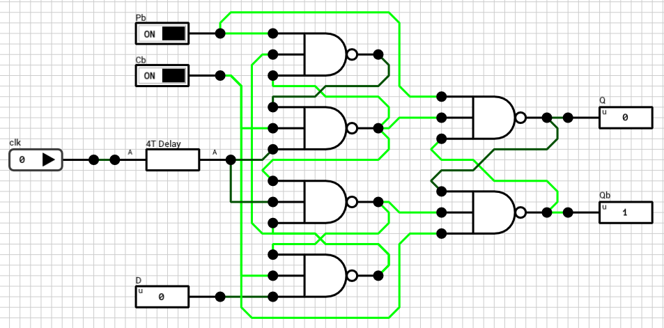
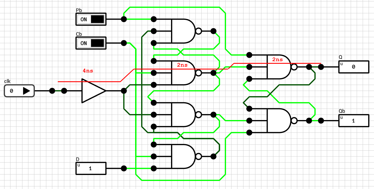
In DLS there’s no such component. You have to create your own flip flop, out of basic logic gates, and use it to build your counter. Figure 1 shows the positive edge triggered D flip flop I used in previous posts to create the register file.
In most cases, building a counter using this FF will work fine. E.g. if the counter’s output is used as an input to a combinational network with its output value connected to another FF, which will in turn be latched at the next clock tick.
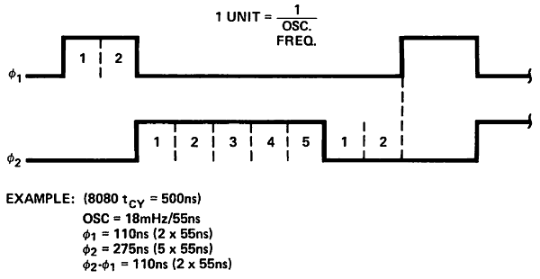
But there’s another use for a counter. You can use a counter to build specific sequences of pulses, such as the two phase clock shown in figure 2. This is the theoretical output of an
i8224. Phase 1 (phi1) is HIGH for 2 clock ticks. It then goes to LOW and phase 2 (phi2) goes to HIGH for the next 5 clock ticks. After that, both phases are LOW for 2 extra ticks.
In order to build such clock, we can use a mod-9 counter (since there are 9 ticks in a cycle). A mod-9 counter counts from 0 to 8 and then wraps around. Figure 3 shows the schematic of the counter. Note that since the maximum value of 8 requires 4 bits, there are 4 flip flops in the schematic.
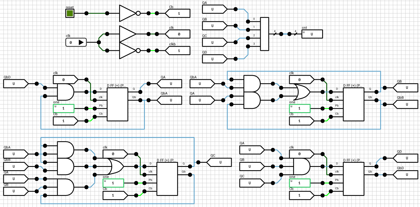
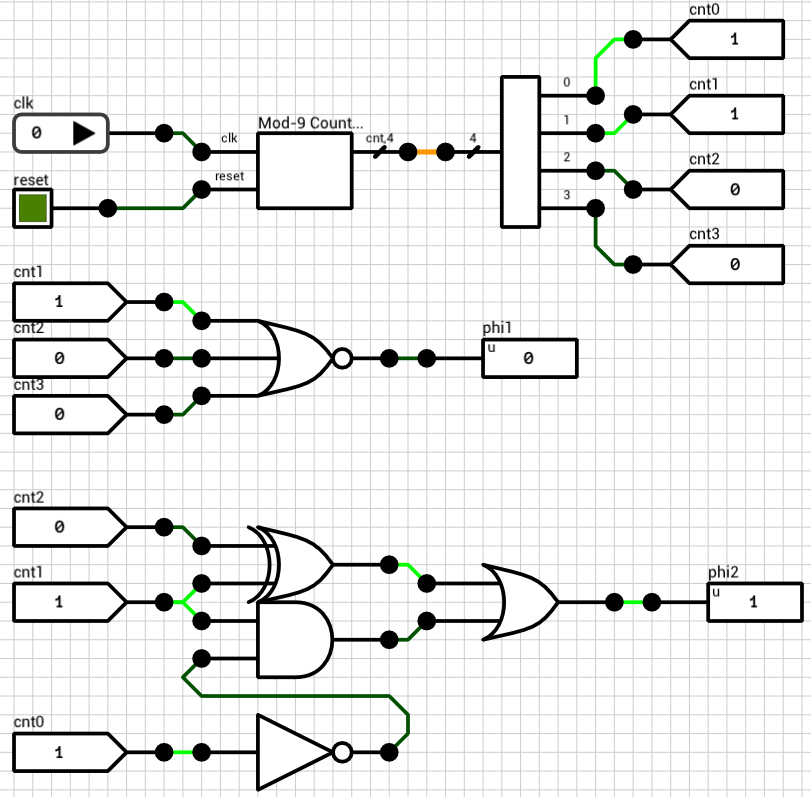
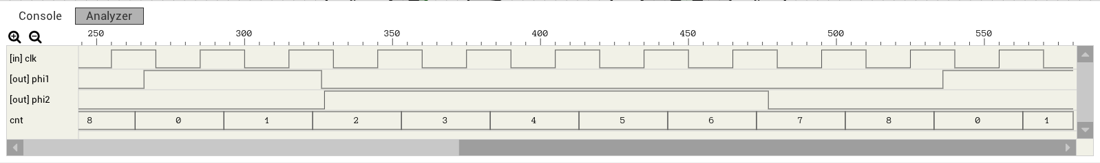
Figure 4 below shows the two phase clock circuit using the mod-9 counter. Phase 1 is HIGH when cnt is 0 or 1. Otherwise it’s LOW. Phase 2 is HIGH when cnt is 2, 3, 4, 5 or 6, otherwise it’s low. The two outputs, phi1 and phi2 are used as clock inputs to an i8080 CPU.
Theoretically, everything should work correctly if we use the FF from figure 1. The counter should count from 0 to 8, phi1 and phi2 will be calculated based on the counter’s value and the i8080 should function as expected. Unfortunately, this isn’t the case (otherwise I wouldn’t have written this :)). Let’s take a look at the timing output of the circuit from figure 4, where the mod-9 counter has been implemented using the FF from figure 1.
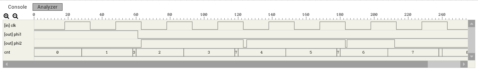
phi1 looks correct. But phi2 has 2ns spikes every time the next counter value requires 2 bits to be flipped (e.g. from 1 to 2, bit #0 should go from HIGH to LOW and bit #1 should go from LOW to HIGH). This is because the FF from figure 1 has a different clk-to-Q propagation delay depending on whether Q is going to rise (0 to 1) or fall (1 to 0). Figures 6 and 7 show the critical path for both cases.
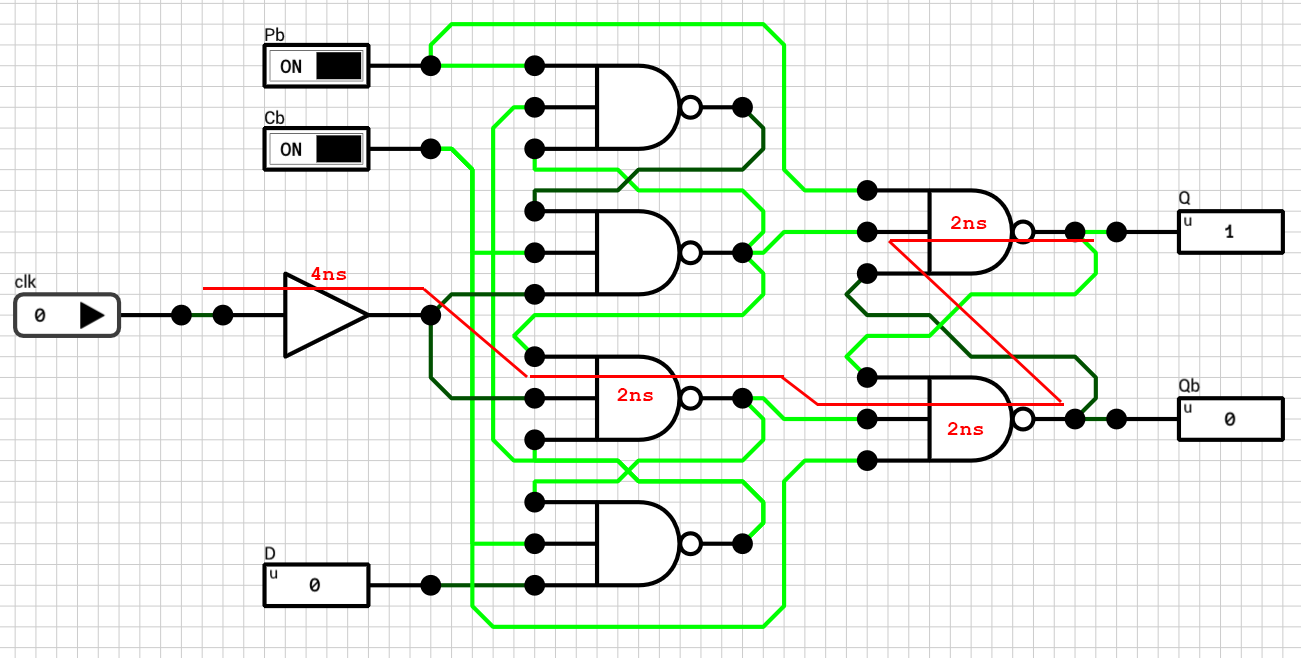
When Q is going to rise, the rising edge of the clk requires 8ns to reach it. When Q is going to fall, the clk signal requires 10ns to reach it. There is a 2ns difference between the two cases and this is the reason for the spikes in figure 5. The mod-9 counter generates the sequence 0, 1, 3, 2, 3, 7, 4, 5, etc., instead of the expected sequence of 0, 1, 2, 3, 4, 5, etc., because bits go from LOW to HIGH faster than they go from HIGH to LOW.
The fix is easy given the paths from figures 6 and 7. The best we can do is to make the fast path a bit slower. This can be achieved by inserting a 2ns buffer as shown in figure 8.
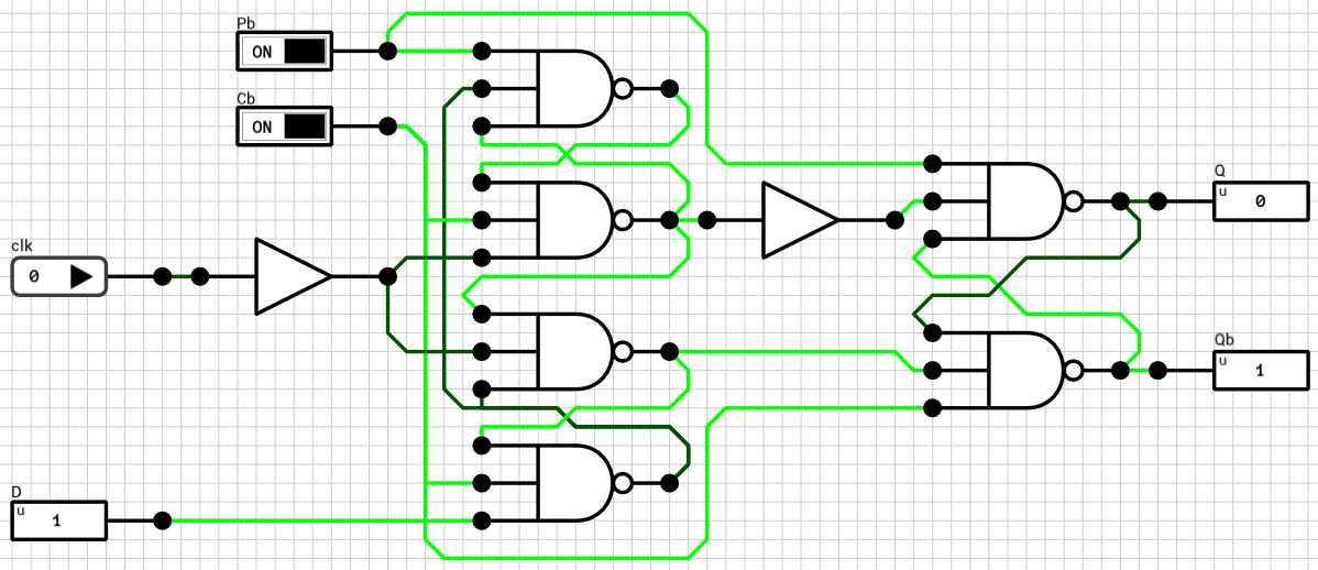
Figure 9 shows the timing graph of the two phase clock using a mod-9 counter implemented with the FF from figure 8.
Note: The final FF from figure 8 still includes the 4ns buffer after the clk which I added in a previous post for the register file. This buffer is used to synchronize clk and D in case both of them switch at the same time. In other words, it makes the setup time of the FF equal to 0 (tS = 0). In the counter case, this delay shouldn’t be needed. By removing the buffer, the FF’s propagation delay can be reduced to 6ns instead of 10ns. This means that the counter can work with a faster clock.
Thanks for reading. Comments/suggestions/corrections are welcome.